Heisenberg
Essentials
Heisenberg is a four-operator phase-modulation synthesizer (PM), offering FM-like tones through flexible sound design capabilities.
Flexible modulation matrix for complex routing
Assignable envelopes for dynamic control
Multiple LFOs for modulation
Multimode filter for tone shaping
Ideal for digital pianos, bells, basses, and experimental textures.
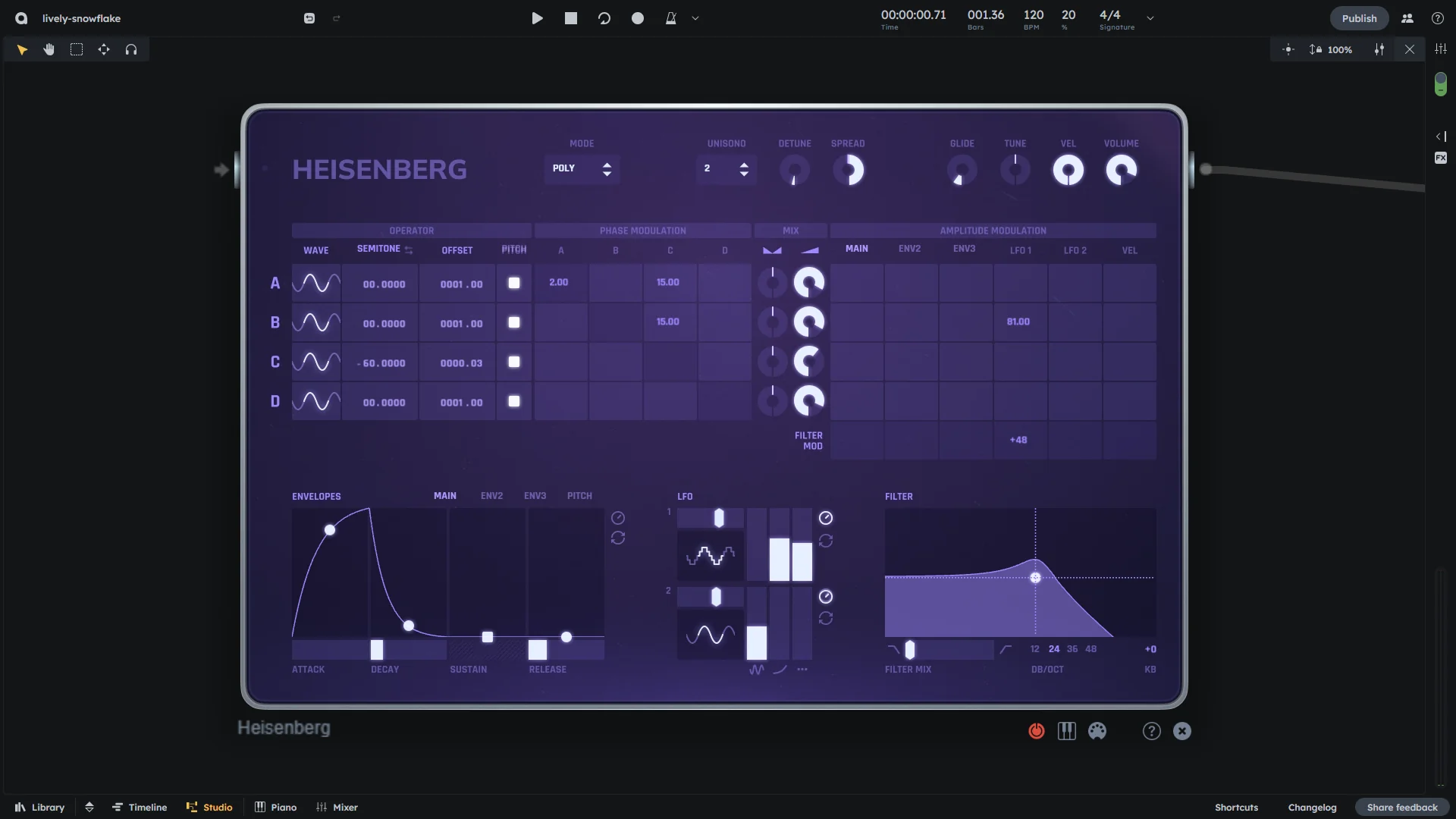
Global Controls
Mode |
Play mode:
|
|---|---|
Unisono |
Amount of unison voices per note (1-4). Values > 1 create multiple voices for fatter, wider sounds |
Detune |
Tuning of unison voices in semitones (0-1 semitones). Creates detuning between voices when unisono > 1 |
Spread |
Stereo width of unison voices (-100 to 100%). 0 = centered, positive = spread right, negative = spread left |
Glide |
Portamento time between notes (0-5000 ms). In Mono/Legato mode, notes glide if they overlap; in Polyphone mode, notes glide if they don’t overlap |
Tune |
Global pitch adjustment in semitones (-12 to +12 semitones) |
Velocity |
Global velocity sensitivity multiplier (0-100%). Controls how much note velocity affects loudness |
Volume |
Overall output level (0-1, equivalent to -∞ to 0 dB) |
Active |
Enable/disable the device (). When disabled, the synthesizer is silent |
Detune Mode |
Controls how operator detune is displayed: Semitone (1) or Ratio (2) mode (1-2). This affects the display only, not the audio behavior |
Micro-tuning |
Optional micro-tuning reference. Links to a micro-tuning device for alternative tuning systems |
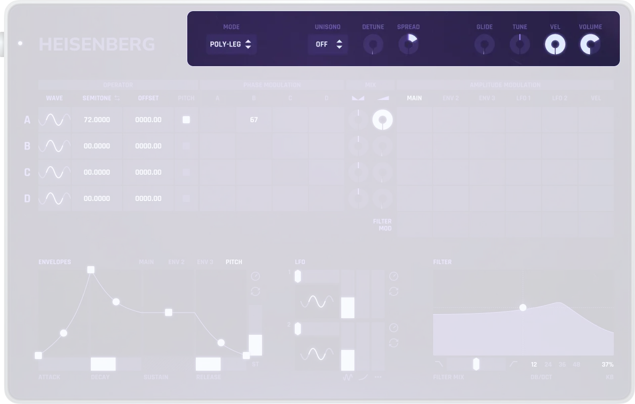
Operator (A–D)
Each operator can act as either a carrier (sound generator) or a modulator (affecting another operator’s sound). Every operator has individually controllable parameters.
Wave |
Choose waveform from 49 selectable waves like sine, square, sawtooth, triangle, etc. |
|---|---|
Semitone/Ratio |
Coarse pitch adjustment. Can be displayed as semitones (0-64) or frequency ratio, depending on operator detune mode setting |
Offset |
Fine pitch adjustment in Hz (-9999.99 to 9999.99 Hz) |
Pitch |
Enables the pitch envelope for this operator |
The waveform significantly affects the character of modulation. Sine waves produce clean, harmonic sounds, while complex waves introduce richer overtones.
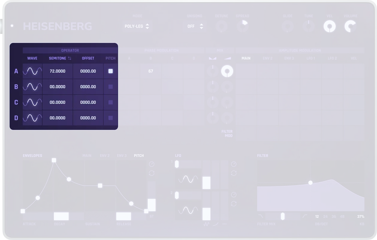
Phase Modulation
At the heart of the interface is the modulation matrix, where you define which operator modulates which.
Instead of altering pitch, PM changes a signal’s phase over time. When the phase of a carrier is modulated by another operator (the modulator), new harmonics are created, making the sound more complex or animated.
Unlike subtractive synthesis (which removes harmonics via filters), phase modulation adds harmonics through modulation. This results in metallic, bell-like, or digital textures that are difficult to achieve with analog-style filtering.
The matrix works like a grid:
Rows = Carriers (operators producing the final sound)
Columns = Modulators (operators modifying other operators)
Each cell in the matrix holds a value (e.g., 0.5 or 1.0) that determines how much one operator modulates another.
Example
In row A, column B, the value is “0.7”: This means B modulates A with a depth of 0.7
You can combine them freely:
A modulator can affect multiple carriers
A carrier can be affected by multiple modulators
Chained or circular modulations are possible: e.g., C -> B -> A or even A -> B -> C -> A (feedback)
Visual Analogy
Think of each operator as a light source
Modulation is like placing colored filters in front of that light
The more filters (i.e., modulators) in the chain, the more colorful, complex, or unpredictable the result becomes
Mix
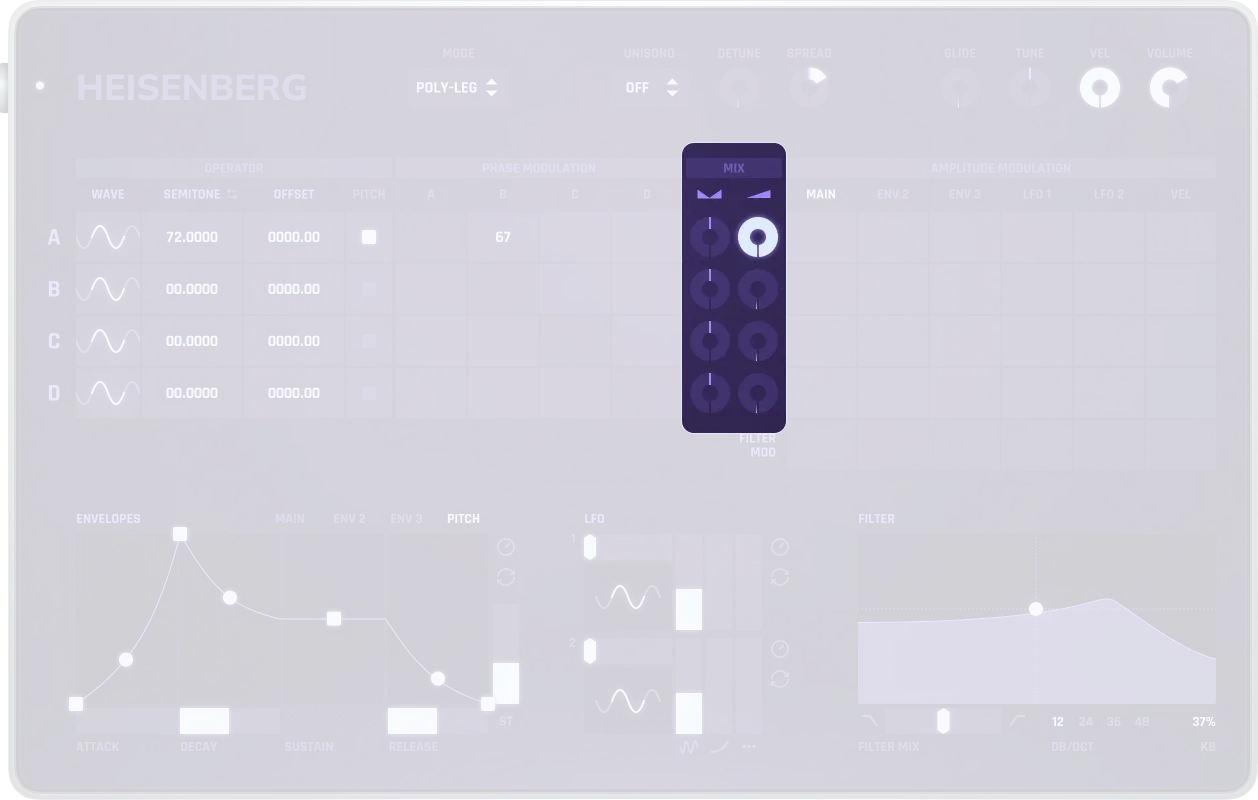
Pan (left knob) |
Stereo placement (-100 to 100). -100 = fully left, 0 = centered, 100 = fully right |
|---|---|
Volume (right knob) |
Audio output level of the operator (0-1, equivalent to -∞ to 0 dB). Only affects audible output, not modulation |
These only affect the audible output, not modulation.
Default Behavior
When loading a new patch, only Operator A has Volume > 0 (audible)
Operators B, C, and D are muted (Volume = 0) by default and typically serve as modulators
Amplitude Modulation
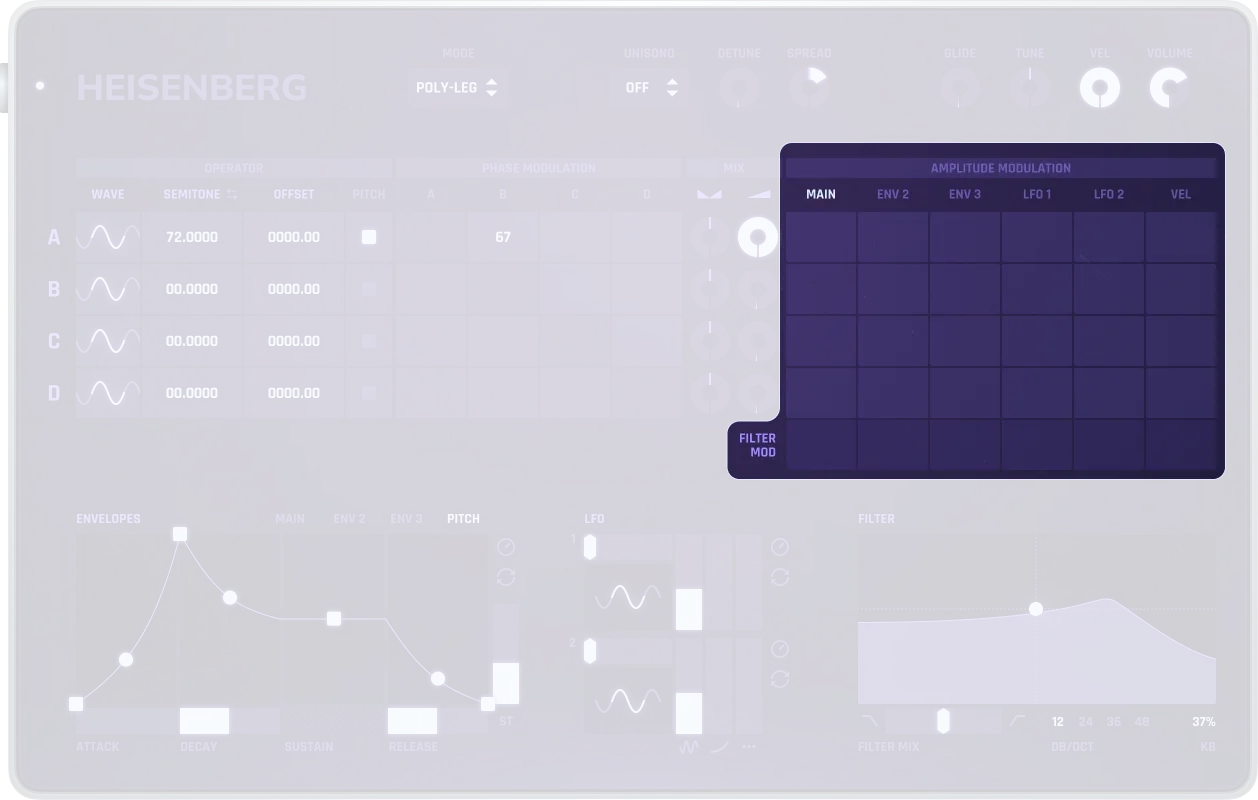
Rows |
Operators A–D and Filter Mod |
|---|---|
Columns |
Mod sources (Main ENV, ENV2, ENV3, LFO1, LFO2, Velocity) |
Function |
Controls how strongly each source modulates an operator’s amplitude or the filter cutoff |
Filter Mod |
Bottom row controls how modulation sources affect the filter |
Envelopes
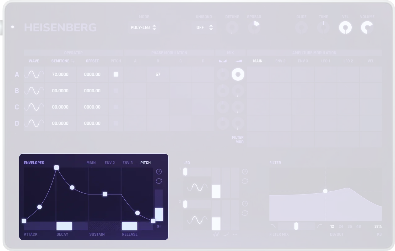
Main ENV |
Standard ADSR envelope. Always applied to overall gain, but can also be assigned to individual operators via the amplitude modulation matrix |
|---|---|
ENV2 & ENV3 |
Freely assignable ADSR envelopes. Can be routed to operator amplitude, filter cutoff, or other destinations via the amplitude modulation matrix |
Pitch Envelope |
Dedicated pitch envelope. Can be enabled per operator to modulate pitch over time |
Loop |
All envelopes can loop for rhythmic or evolving modulation patterns |
LFO
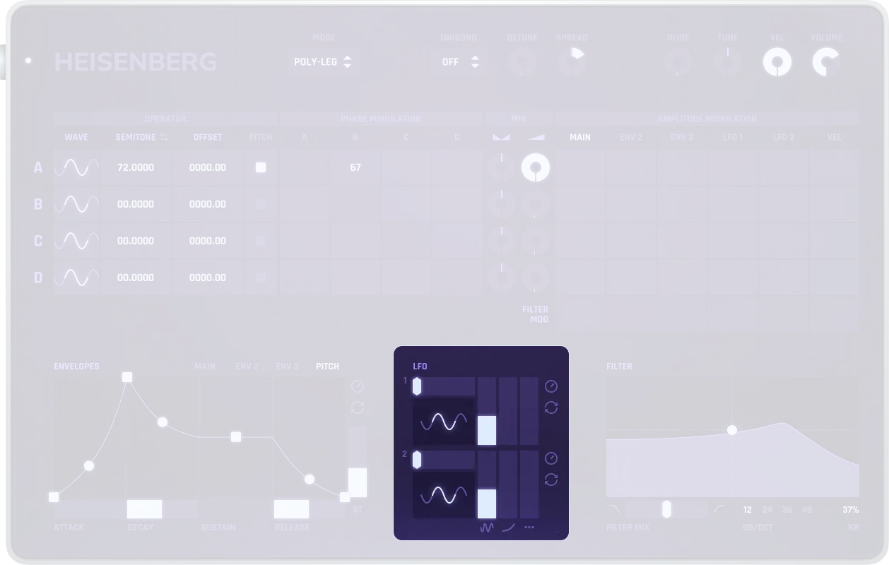
Waveforms |
Selectable waveforms including sine, square, saw, triangle, parabola, etc. |
|---|---|
Rate |
LFO speed. When free-running: 0.01-500 Hz ( normalized). When synced: quantized to bar time durations from 1/256 to 4/1 bars |
Sync |
Free-running or synced to host tempo. When synced, rate is quantized to one of 30 tempo-based values |
Destinations |
Can modulate pitch, amplitude, filter cutoff, etc. via the amplitude modulation matrix |
Filter
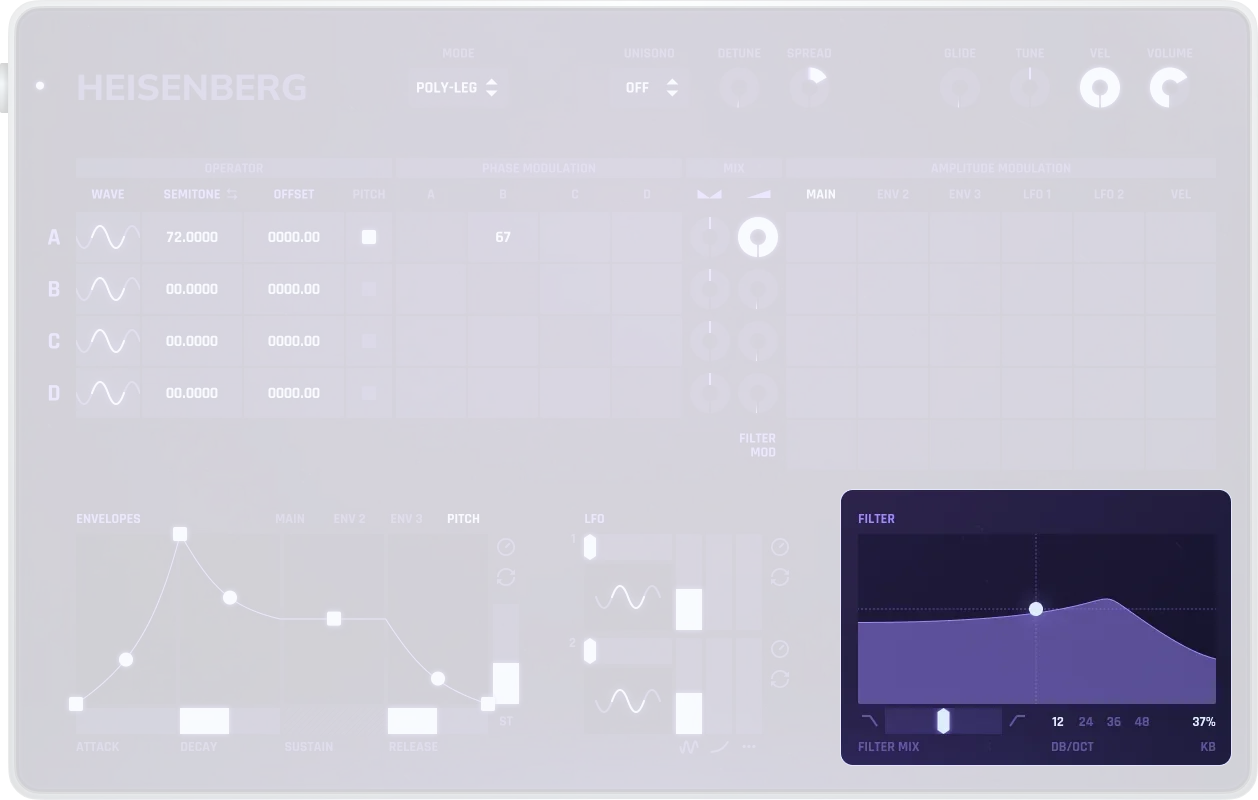
Type |
Multimode filter type (continuous: -1 = Low-pass, ~0 = Shelf, 1 = High-pass) |
|---|---|
Slope |
Filter order/slope: 12 dB , 24 dB, 36 dB, or 48 dB per octave |
Cutoff |
Filter cutoff frequency (33-22500 Hz) |
Resonance |
Filter resonance/Q factor (0.707 to 60). Higher values create more emphasis at the cutoff frequency |
Keytracking |
Adapts cutoff frequency to keyboard pitch (modulation depth: -1 to 1) |
Envelope Modulation |
Main ENV, ENV2, and ENV3 can modulate filter cutoff (modulation depth: -1 to 1 for each) |
LFO Modulation |
LFO1 and LFO2 can modulate filter cutoff (modulation depth: -1 to 1 for each) |
Velocity Modulation |
Note velocity can modulate filter cutoff (modulation depth: -1 to 1) |
Step-by-step Modulation Setup
Set up your first phase modulation patch step by step.
Make sure Operator A is audible (Volume > 0).
Enter a value in the matrix, e.g., B -> A = 0.5.
Listen to how A’s tone changes.
Add another layer: C -> B = 0.8 -> now you get indirect modulation from C to A.
Note: Only the values in this matrix control modulation depth. The Volume sliders do not affect modulation.
Use Cases
Digital E-Piano |
A = sine (carrier), long release; B = square (modulates A); ENV2 = velocity-sensitive amplitude |
|---|---|
Synth Kick |
A = sine, pitch envelope active with steep drop; Short amplitude envelope |
Bell Tone |
A = sine (carrier); B = square (modulator), high ratio; ENV3 modulates filter cutoff slightly |
Practical Tips
Practical Tips
Mod depth controls harmonic complexity; start low and increase gradually.
Use ENV loop for rhythmic modulation; sync LFOs to host tempo when needed.
Keep only one operator audible at first; add modulators step by step.
Keytrack the filter for playable patches; combine with velocity in the mod matrix.